Sciences & Technology
Research study on Center of Mass measurement in golf swing
Abstract
Smart2Move, specialist in Ground Reaction Force in golf since many years, has decided to make a scientific study to verify if the position of the Center of Mass during a golf swing can be accurately estimated only by 3D Ground Reaction Force data. This type of method has been used and proven for simple tasks like walking or jumping by the scientific community, but we have not found any study applying these techniques to golf and proven by scientific studies.
After measuring over 300 swings with different players using different clubs, and comparing the results obtained on CoM position from 3D Force plates method and simultaneously with Motion Capture system, the results are showing the method is not valid, the error is too big.
The following article explain the study, and a video that has been presented to the 2021 Congress of ECSS (European College of Sport Sciences) detailing the protocol and results obtained is available on our webinar page
A golf swing requires stability and force to produce motion and generate club head speed by controlling ball trajectory! The right mix between force and stability can be analysed in biomechanics by analysing the relationship between the 3D Ground Reaction Force vectors and the centre of mass of the golf player.
The GRF (Ground Reaction Force) global vector represents the overall external forces applied by the ground on the golfer, through the principle of the third law of newton (or “action – reaction” law). It shows in which direction and how much force is applied on the golfer from the ground.
The CoM (Center of Mass) is the term given to the point where the weighted relative position of the distributed mass sums to zero, or the point where if a force is applied, it causes it to move in the direction of force without rotation. It represents a hypothetical point where the entire mass of an object / body, or system made by object(s) and body(ies), may be assumed to be concentrated to visualize its motion.
To sum up how the GRF vector can affect the golfer’s system (including the golf club), it’s interesting to measure the effect of GRF forces on the CoM of the golfer, as well as the overall motion of the body or some of the segment(s) of the player, including the club.
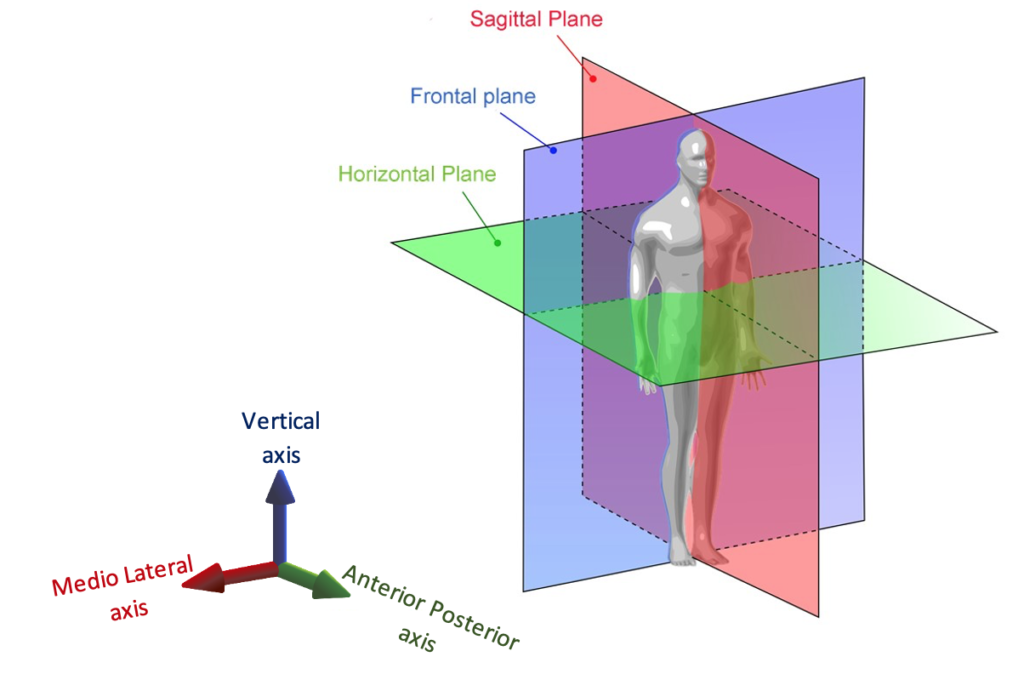
Reminder on 3D axis and 3D plan of Human body:
In the following picture, during downswing, we can observe the GRF vector pointing on the left side of the player representing a net force of 1520 Newtons, while the CoM is still positioned slightly on the right side of the player at a distance of 5 cm (perpendicularly to the vector direction). Therefore, in the frontal plane, the GRF vector apply a torque on the Golfer CoM (applying a linear force away from the CoM of the player). The equation of the torque equal to the moment arm (perpendicular distance between the force vector and the CoM position in meter) multiplied by the force (length of the vector in frontal plane in newtons). This torque generated in golfer frontal plane tends to rotate the entire system (or at least some parts of the system) as indicated by the curved arrows.
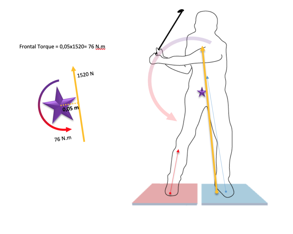
To increase the torque, so the rotational force applied to the golfer in frontal plane in this example, there are 2 possibilities:
- Increase the magnitude of the force
- Increase the moment arm (distance between GRF vector and CoM)
Or, of course, both solution at the same time!
Knowing the GRF and the CoM position reveals an enormous amount of data that can explain part of the performance to generate Club Head Speed when the player is able to transfer the torque to the arms and club displacement through his or her body motion. It also indicates the forces that tends to destabilize the player and could create some imbalance…
To measure 3D Ground Reaction Force, we know you need a 3D force plates. But, the question is, how can you get the CoM position during a golf swing?
From February 2021 to August 2021, a scientific study has been conducted by the laboratory of Aix-Marseille University of Sports by an engineer in human motion and sports science (Mr M. Gomez) supervised by the University Institute of Sports. The goal of this scientific study was to compare the displacement of the center of mass of a golfer during a swing using two methods:
- A kinematic system, based on multiple high speed cameras system (Qualysis) and considered as reference in golf sciences literature. This system measure the position of each joint, and knowing the mass of every segments, it allows to obtain the Global CoM.
- A kinetic system, 3D force plate (Kistler) and a method of CoM determination already used and proven to calculate CoM displacement for gait analysis.
This second method is based on the law of motion formula (second law of Newton): Force = Mass x Acceleration. The principle is based on the mathematical relation between position, velocity and acceleration. Basically, if you calculate the integral of the acceleration of a point, you can obtain its velocity. And if you calculate the integral of the velocity of this point, you can get its position. Please notice these methods can only work if the force plates are installed on a perfect horizontal surface.
So using the Ground Reaction Force data provided by 3D force plate, and using a double integration of these forces, we can expect to get the position and displacement of the Center of Mass of an object / subject, by knowing where is the initial position of the CoM before the motion is initiated.
This method has been used successfully on several scientific studies, to estimate the CoM position for postural tasks, gait tasks (walking) and even running tasks. You can find below some links and references of these scientific publications.
N.B.: A third method to estimate CoM displacement based on CoP displacement also exists, but this has not been validated for dynamic motion, only used in static motion and balance studies.
To validate the choice of this method with double integration of 3D GRF, we have tested the protocol with a running task. You can observe on the graphs below, the CoM displacement in millimeters for a running task with the Kinematic system (in blue) and with the kinetic system (in red) on vertical axis.
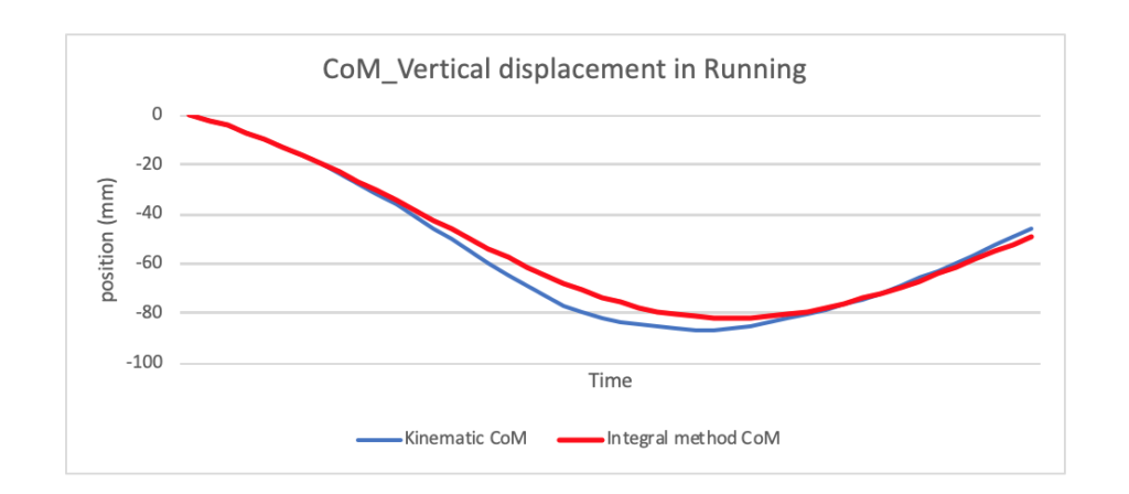
The difference between the 2 curves is minimal, and this double integration method to estimate CoM displacement for motion such as running is considered as valid, as demonstrated in literature. We observe a maximum difference of 7mm on a full displacement of 125mm.
Then we decided to apply the same method for a population of 11 adults and valid golfers, with a max index of 27. Each player had performed around 10 good swings with their wedge (60 yards carry target), 10 good swings with their 7 iron (full swings with target), and 10 good swings with their driver (full swings with target).
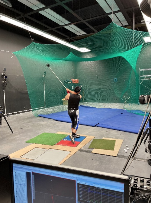
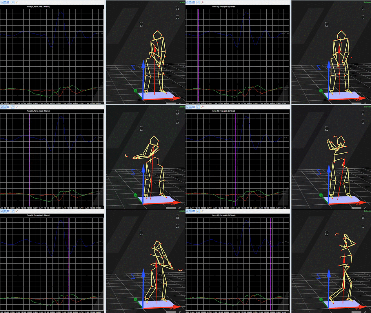
After having computed these 330 swings measured at the same time with the Kinematic system and the 3D Force plate, we have made a statistics study to estimate the validity of the method of double integration and the refence method with kinematic system.
On the following table of results, you have the summary of the results.

The first type of statistics, in the first column, is called the RMS (Root Mean Square), and indicates the average difference in millimetres of CoM displacement between the 2 methods of measurement. The first number, “40,6” means you have an average difference of 40,6 mm (with a standard deviation of + / 24 mm) between the CoM displacement measured with the 2 different methods on the ML (Medio lateral) axis with the Driver. In the second column, this value is compared to the overall length of displacement of the CoM for Driver in ML axis, meaning that 40,6 mm difference corresponds at 23,2 % of the total displacement, which can be considered as an error of 23,2 % in CoM position calculated vs measured.
The results are showing the same values for the 3 types of clubs following the 3 axis. We observe an error quantified between 20 % to 25% on the ML (Medio-latera) and Vertical axis with all clubs, and an error between 61% and 81% on AP (Anterior posterior) axis…
The third column presents the results of coefficient of Spearman, a statistic test that assesses how well the relationship between to variables can be described using a monotonic function. If the result of this test is equal to 1, the two variables are identical. When the coefficient is between 0.95 and 1, the correlation very good (so acceptable in sciences), between 0.9 and 0.95, the correlation is good (potentially acceptable in sciences). Below 0.9, the correlation is not acceptable, meaning the 2 variables are too different to be comparable. Thus, a high corelation means the CoM measured or calculated tend to move in the same direction, while a low coefficient means the CoM are not moving in the same direction through the swing.
In our results, we observe quite a good corelation on vertical axis: 0.96 for Drivers (very good), 0.92 with 7 irons, and 0.88 for wedges. On the ML axis, the coefficients are around 0.80, but not high enough to be comparable. On the AP axis, coefficient is cloth to 0 as the difference is too big to observe any correlation between the 2 methods.
At this point, we can definitely conclude that the method based on 3D GRF to measure the CoM displacement is not valid for a golf swing, the difference with the reference kinematic system is too big to estimate with enough accuracy the CoM position. In fact, CoM calculated with 3D force plates for a motion like a golf swing is invalid and false, a kinematic method is required to get properly the CoM position of a golfer.
Statistics results are not the most evident to read and visualise, so please find below one example of the 330 swings extract from the study to show in reality the difference in position of CoM measured and calculated on each axis, and displacement on the 3 plans.
The 3 graphs below represent the Displacement of CoM through time for on the 3 axis (same as example showed for running test vertical earlier).
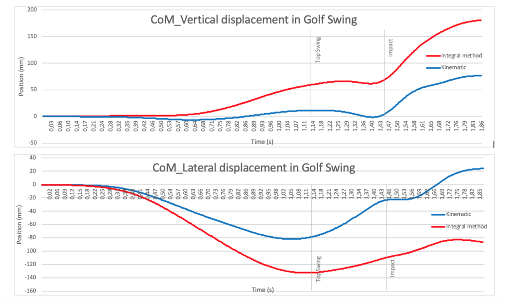
With this example, the shape of curves in vertical and in lateral axis are similar but the amplitudes are different. At the top of the swing, the double integration method has overvalued the CoP displacement around 45mm on vertical axis, and around 56mm on lateral displacement. At impact, the overestimation is even bigger, with around 64mm on vertical axis and around 85mm on lateral axis.
On the anteroposterior axis, we can observe the shape are not following the same changes, this explains the very bad correlation coefficient observed in statistics. Once again, in this example, the method of double integration of 3D GRF gives overvalued data.

Let’s use the same example and the same data, but this time the 3 graphs below represent the CoM displacement in the 3 planes:
- Frontal, it’s like if you were watching the player facing him
- Sagittal, it’s like if you were watching the player from down the line
- Horizontal, it’s like if you were watching the player from the sky or a helicopter
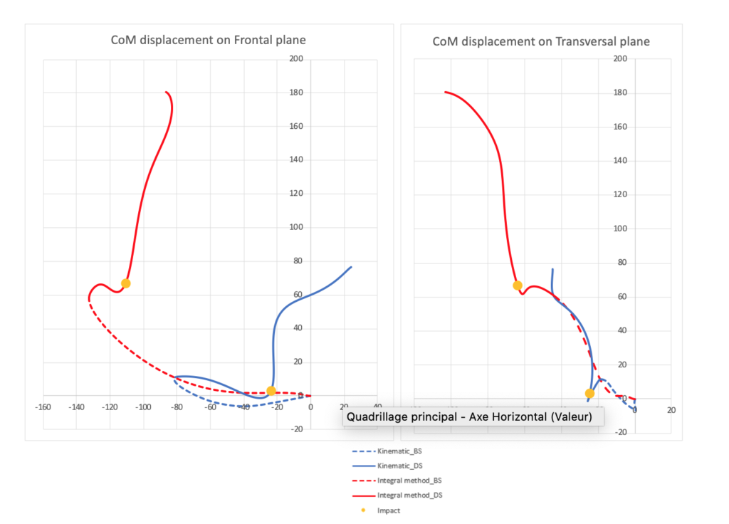

These graphic representations show the important difference you can obtain by using the method of measuring the CoM with a kinematic system and calculate it from 3D GRF method with double integration.
Finally, and to understand how much the accuracy of the position of the CoM is crucial to give data such as the frontal torque explained at the first part of this article, let’s make the same calculation at the downswing position while the error overestimates the CoM position 130mm away from the GRF vector:
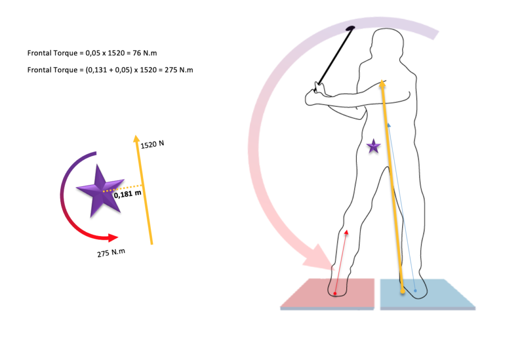
NB: As a consequence, If the value calculated for the CoM is underestimated more than 60 mm, the CoM would be now on the left side of the player and you will obtain a torque in frontal plane of (-0.01) x 1520= -15.2 N.m!
The variability of results between all players and all swing does not allow to estimate a constant error that could improve the CoP position estimated with the 3D GRF double integration method, as a consequence and to date, the only reliable and correct way to get the CoM for a golfer is to use a kinematic system scientifically validated.
Jean-Paul Fernandez
Sport Scientist
R&D Manager for Smart2Move
– September 2021-
Appendices
Thank you to:
M. Gomez for all his work in 2021 to conduct this Study.
Pr. G. Rao for his time, his integrity, and his investment in this project.
The “Institut des Sciences du Mouvement » & Sport Science University of Aix Marseille to host this program.
M. F. Laborde for his support along this project.
Smart2Move who has financed the project.
All participants of these studies and collaborators from Laboratory.
References / articles:
- King, D., & Zatsiorsky, V. (1997). Extracting gravity line displacement from stabilographic recordings. Gait & Posture, 6(1), 27-38.https://doi.org/10.1016/S0966-6362(96)01101-0
- Levin, O., & Mizrahi, J. (1996). An iterative model for estimation of the trajectory of center of gravity from bilateral reactive force measurements in standing sway. Gait & Posture, 4(2), 89-99. https://doi.org/10.1016/0966-6362(95)01037-8
- Morasso, P. G., Spada, G., & Capra, R. (1999). Computing the COM from the COP in postural sway Movements. Human Movement Science, 18(6), 759-767. https://doi.org/10.1016/S0167-9457(99)00039-1
- Shimba, T. (1984). An estimation of center of gravity from force platform data. Journal of Biomechanics, 17(1), 53,59-57,60.https://doi.org/10.1016/0021-9290(84)90080-0
- Zatsiorsky, V. M., & King, D. L. (1998). An algorithm for determining gravity line location from posturographic recordings. Journal of biomechanics, 31(2), 161–164. https://doi.org/10.1016/s0021-9290(97)00116-4
- Lafond, D., Duarte, M., & Prince, F. (2004). Comparison of three methods to estimate the center of mass during balance assessment. Journal of biomechanics, 37(9), 1421–1426. https://doi.org/10.1016/S0021-9290(03)00251-3
- Gutierrez-Farewik, E. M., Bartonek, Å., & Saraste, H. (2006). Comparison and evaluation of two common methods to measure center of mass displacement in three dimensions during gait. Human Movement Science, 25(2), 238-256.https://doi.org/10.1016/j.humov.2005.11.001
- Gatt, C., Pavol, M., Parker, R., & Grabiner, M. (1998). Three-dimensional knee joint kinetics during a golf swing – influences of skill level and footwear. The American Journal of Sports Medicine, 26(2), 285-294.https://doi.org/10.1177/03635465980260022101
- de Leva, P. (1996). Adjustments to zatsiorsky-seluyanov’s segment inertia parameters. Journal of Biomechanics, 29(9), 1223-1230. https://doi.org/10.1016/0021-9290(95)00178-6
- Gard, S. A., Miff, S. C., & Kuo, A. D. (2004). Comparison of kinematic and kinetic methods for computing the vertical motion of the body center of mass during walking.Human Movement Science, 22(6), 597-610.https://doi.org/10.1016/j.humov.2003.11.002
